Code file for this section is 15-draw_cube.cpp
You're almost done!
Here are the final steps needed to get your Vulkan image up onto the screen:
Before starting to draw anything, the sample program needs a target swapchain
image to render into.
The vkAcquireNextImageKHR() function is used to get an index into the
swapchain image list, so it knows which framebuffer to use as a rendering target.
This is the next image that is available for rendering.
res = vkCreateSemaphore(info.device, &imageAcquiredSemaphoreCreateInfo,
                        NULL, &imageAcquiredSemaphore);

// Get the index of the next available swapchain image:
res = vkAcquireNextImageKHR(info.device, info.swap_chain, UINT64_MAX,
                            imageAcquiredSemaphore, VK_NULL_HANDLE,
                            &info.current_buffer);
For the first frame, using the semaphore is probably not needed because all the images in the swapchain are probably available. But it is still good practice to make sure that the image is ready before proceeding with the actual submission of commands to the GPU, which we do a bit later. And if this sample were changed to render multiple frames, as in an animation, then it becomes necessary to wait until the hardware is finished with an image before using it again.
Note that you are not waiting for anything now. You are just creating this semaphore and associating it with the image so that the semaphore can be used to postpone the submission of the command buffer until the image is ready.
You have already defined the render pass in a previous section, so starting the render pass by putting a begin render pass command in the command buffer is straightforward:
VkRenderPassBeginInfo rp_begin;
rp_begin.sType = VK_STRUCTURE_TYPE_RENDER_PASS_BEGIN_INFO;
rp_begin.pNext = NULL;
rp_begin.renderPass = info.render_pass;
rp_begin.framebuffer = info.framebuffers[info.current_buffer];
rp_begin.renderArea.offset.x = 0;
rp_begin.renderArea.offset.y = 0;
rp_begin.renderArea.extent.width = info.width;
rp_begin.renderArea.extent.height = info.height;
rp_begin.clearValueCount = 2;
rp_begin.pClearValues = clear_values;
vkCmdBeginRenderPass(info.cmd, &rp_begin, VK_SUBPASS_CONTENTS_INLINE);
Note that you already created a command buffer and put it in recording mode by calling
init_command_buffer() and execute_begin_command() earlier in this sample.
You supply the previously-defined render pass and the framebuffer selected by the
index returned from vkAcquireNextImageKHR().
The clear values were initialized to set the background color to a very dark grey and the
depth buffer to its "far" value (clear_values).
The rest of the needed information is in info.render_pass as you set up before, and you then
go ahead and insert this command to start the render pass into the command buffer.
Next bind the pipeline to the command buffer with:
vkCmdBindPipeline(info.cmd, VK_PIPELINE_BIND_POINT_GRAPHICS, info.pipeline);
You defined the pipeline in the previous section and binding it here tells the GPU how to render the graphics primitives that are coming later.
VK_PIPELINE_BIND_POINT_GRAPHICS tells the GPU that this is a graphics pipeline
instead of a compute pipeline.
Note that since this command is a command buffer command, it is possible for a program to define several graphics pipelines and switch between them in a single command buffer.
Recall that the descriptor set we defined earlier described how the shader program expects to find its input data, such as the MVP transform. Give that information to the GPU here:
vkCmdBindDescriptorSets(info.cmd, VK_PIPELINE_BIND_POINT_GRAPHICS,
                        info.pipeline_layout, 0, 1,
                        info.desc_set.data(), 0, NULL);
Again note that you could bind different descriptors in the middle of a command buffer if you wanted to change how the shader program finds its data. For example you could use a different descriptor to point to a different MVP transform if you wanted to change the transform in the middle of a command buffer.
You created a vertex buffer and filled it with vertex data back in the vertex_buffer sample. Here, tell the GPU how to find it:
const VkDeviceSize offsets[1] = {0};
vkCmdBindVertexBuffers(info.cmd, 0, 1, &info.vertex_buffer.buf, offsets);
This command binds the vertex buffer or buffers to the command buffer. In this case, you bind only one buffer, but it could be used to bind many.
You indicated earlier that the viewport and scissors were states that are dynamic,
which means that they can be set with a command buffer command.
So, you need to set them here.
Here's the code in init_viewports() that sets the viewport:
info.viewport.height = (float)info.height;
info.viewport.width = (float)info.width;
info.viewport.minDepth = (float)0.0f;
info.viewport.maxDepth = (float)1.0f;
info.viewport.x = 0;
info.viewport.y = 0;
vkCmdSetViewport(info.cmd, 0, NUM_VIEWPORTS, &info.viewport);
The code for the scissors rectangle is similar.
It is probably good to make these dynamic because many applications need to change these values if the window changes in size during execution. This avoids having to rebuild the pipeline when the window size changes.
Finally, issue a draw command to tell the GPU to send the vertices into the pipeline and finish the render pass.
vkCmdDraw(info.cmd, 12 * 3, 1, 0, 0);
vkCmdEndRenderPass(info.cmd);
The vkCmdDraw command tells the GPU to draw the 36 vertices once.
You already configured the primitive assembly part of the pipeline to draw a list of
independent triangles, so this means drawing 12 triangles.
The vkCmdEndRenderPass command signals the end of the render pass,
but the command buffer is still "open" and the sample is not finished recording commands.
While the GPU is rendering, the target swapchain image layout is
VK_IMAGE_LAYOUT_COLOR_ATTACHMENT_OPTIMAL,
which is the best layout for the GPU rendering.
You set this layout in the subpass definition when you defined the render pass
in a previous section of this tutorial.
But this layout may not be the best layout for the display hardware that scans the image out to the
display device.
For example, the optimum GPU memory layout for rendering might be "tiled",
as discussed in the render_pass section of this tutorial.
But the display hardware may prefer a linear memory layout for scanning out the memory to the
display hardware.
You use the VK_IMAGE_LAYOUT_PRESENT_SRC_KHR layout to specify that the image is about to
be presented to the display.
You already took care of this layout transition in the render pass section by
specifying the finalLayout as VK_IMAGE_LAYOUT_PRESENT_SRC_KHR in the
description of the color image attachment:
VkAttachmentDescription attachments[2];
attachments[0].format = info.format;
attachments[0].samples = NUM_SAMPLES;
attachments[0].loadOp = VK_ATTACHMENT_LOAD_OP_CLEAR;
attachments[0].storeOp = VK_ATTACHMENT_STORE_OP_STORE;
attachments[0].stencilLoadOp = VK_ATTACHMENT_LOAD_OP_DONT_CARE;
attachments[0].stencilStoreOp = VK_ATTACHMENT_STORE_OP_DONT_CARE;
attachments[0].initialLayout = VK_IMAGE_LAYOUT_UNDEFINED;
attachments[0].finalLayout = VK_IMAGE_LAYOUT_PRESENT_SRC_KHR;
attachments[0].flags = 0;
Note that there is another way to accomplish this layout transition by recording another
memory barrier command in the command buffer.
This alternate approach may be useful in certain cases, such as in queue
submissions that do not use a render pass.
An example of this situation can be found in the copy_blit_image sample, which is
not part of this tutorial, but can be found in the same folder as these
tutorial samples.
In this sample, you are using a render pass, but you can still use this alternate approach
if you leave the finalLayout for the color attachment the same as initialLayout
in the render_pass sample where you create the render pass:
attachments[0].initialLayout = VK_IMAGE_LAYOUT_COLOR_ATTACHMENT_OPTIMAL;
attachments[0].finalLayout = VK_IMAGE_LAYOUT_COLOR_ATTACHMENT_OPTIMAL;
This then requires you to perform this transition with another pipeline memory barrier,
in much the same way the set_image_layout() performs layout transitions:
VkImageMemoryBarrier prePresentBarrier = {};
prePresentBarrier.sType = VK_STRUCTURE_TYPE_IMAGE_MEMORY_BARRIER;
prePresentBarrier.pNext = NULL;
prePresentBarrier.srcAccessMask = VK_ACCESS_COLOR_ATTACHMENT_WRITE_BIT;
prePresentBarrier.dstAccessMask = VK_ACCESS_MEMORY_READ_BIT;
prePresentBarrier.oldLayout = VK_IMAGE_LAYOUT_COLOR_ATTACHMENT_OPTIMAL;
prePresentBarrier.newLayout = VK_IMAGE_LAYOUT_PRESENT_SRC_KHR;
prePresentBarrier.srcQueueFamilyIndex = VK_QUEUE_FAMILY_IGNORED;
prePresentBarrier.dstQueueFamilyIndex = VK_QUEUE_FAMILY_IGNORED;
prePresentBarrier.subresourceRange.aspectMask = VK_IMAGE_ASPECT_COLOR_BIT;
prePresentBarrier.subresourceRange.baseMipLevel = 0;
prePresentBarrier.subresourceRange.levelCount = 1;
prePresentBarrier.subresourceRange.baseArrayLayer = 0;
prePresentBarrier.subresourceRange.layerCount = 1;
prePresentBarrier.image = info.buffers[info.current_buffer].image;
vkCmdPipelineBarrier(info.cmd, VK_PIPELINE_STAGE_ALL_COMMANDS_BIT,
                     VK_PIPELINE_STAGE_BOTTOM_OF_PIPE_BIT, 0, 0, NULL, 0,
                     NULL, 1, &prePresentBarrier);
The above code is not in this sample, but can be found in the copy_blit_image
sample.
Once this command executes after the end of the render pass, the image buffer is ready to display. And of course, you do not need to transition the depth buffer image layout.
Keep in mind that you have not actually sent any commands to the GPU yet. You have just recorded them into the command buffer. But now you are done recording:
res = vkEndCommandBuffer(info.cmd);
You need to create a fence, which you use to tell when the GPU is done. You need to know when the GPU is done so that you don't start the present to the display too soon.
VkFenceCreateInfo fenceInfo;
VkFence drawFence;
fenceInfo.sType = VK_STRUCTURE_TYPE_FENCE_CREATE_INFO;
fenceInfo.pNext = NULL;
fenceInfo.flags = 0;
vkCreateFence(info.device, &fenceInfo, NULL, &drawFence);
Now we can submit the command buffer:
const VkCommandBuffer cmd_bufs[] = {info.cmd};
VkPipelineStageFlags pipe_stage_flags =
    VK_PIPELINE_STAGE_COLOR_ATTACHMENT_OUTPUT_BIT;
VkSubmitInfo submit_info[1] = {};
submit_info[0].pNext = NULL;
submit_info[0].sType = VK_STRUCTURE_TYPE_SUBMIT_INFO;
submit_info[0].waitSemaphoreCount = 1;
submit_info[0].pWaitSemaphores = &imageAcquiredSemaphore;
submit_info[0].pWaitDstStageMask = &pipe_stage_flags;
submit_info[0].commandBufferCount = 1;
submit_info[0].pCommandBuffers = cmd_bufs;
submit_info[0].signalSemaphoreCount = 0;
submit_info[0].pSignalSemaphores = NULL;
res = vkQueueSubmit(info.queue, 1, submit_info, drawFence);
The VK_PIPELINE_STAGE_COLOR_ATTACHMENT_OUTPUT_BIT is the stage where the final color
values are output from the pipeline. We use the imageAcquiredSemaphore to wait
at the color attachment output stage until the swapchain image is available before
writing colors to it.
When the GPU is done executing the commands, it signals the fence drawFence to
indicate that the drawing is complete.
vkWaitForFences() waits for the command buffer to complete execution.
It is called in a loop here in case the commands take much longer to complete
than expected, which should not be the case in this simple sample.
do {
    res = vkWaitForFences(info.device, 1, &drawFence, VK_TRUE, FENCE_TIMEOUT);
} while (res == VK_TIMEOUT);
At this point, you know that the swapchain image buffer is ready to present to the display.
Presenting the swapchain image to the display is straightforward:
VkPresentInfoKHR present;
present.sType = VK_STRUCTURE_TYPE_PRESENT_INFO_KHR;
present.pNext = NULL;
present.swapchainCount = 1;
present.pSwapchains = &info.swap_chain;
present.pImageIndices = &info.current_buffer;
present.pWaitSemaphores = NULL;
present.waitSemaphoreCount = 0;
present.pResults = NULL;
res = vkQueuePresentKHR(info.queue, &present);
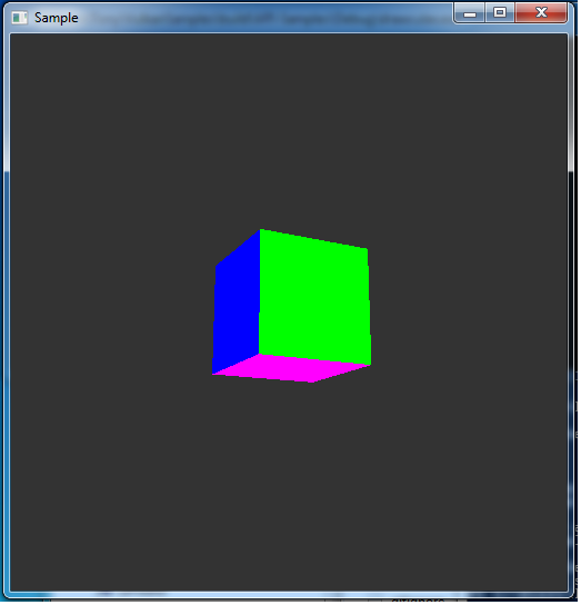
At this point, you should now see a cube on the screen!
| Pipeline | Back to: Index | Next: Vulkan 1.1 |